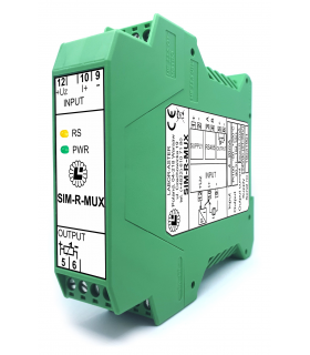

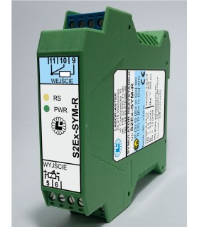
SIMULATOR-R
227.00 €
Resistance, temperature sensor (e.g. Pt100) isolator simulator repeater, digital resistance decade, required constant (at least 2 sec) measurement current of simulated resistance


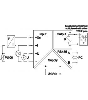
Industrial automation uses a variety of analog signals. These are most often current (0...20mA, 4...20mA) or voltage (0...10V) signals. To monitor process temperature, thermocouple sensors (e.g., K thermocouple) or resistance sensors (e.g., Pt100) are used, also NTC or PTC. Sometimes, the system must decide, for example, whether to activate cooling based on the measurement of its RTD (Resistance Temperature Detector) input, and process temperature information is available only as a 4...20mA current signal or digitally via RS485 Modbus. Often, we also want to protect the controller and avoid directly connecting a Pt100 sensor to its input, which may be susceptible to damage, interference, or lightning strikes, which could damage the controller.
In these cases, it is worth using a resistance simulator Simulator-R, SIM-R-MUX type or an equivalent in an intrinsically safe version with an "ic" input circuit protection level S2Ex-SIM-R.
Due to very different customer needs in terms of the range of simulated resistance and the measuring current flowing from the RTD input, in order to ensure optimal device operation and maximum accuracy, each LABOR-ASTER resistance simulator has hardware configured for each customer.
a) The output simulates the resistance linearly to the input signal (standard version of Simulator-R).
|
Input [V] |
Resistance [Ω] |
Temperature [°C] |
|
0 |
695 |
-60 |
|
5 |
(2407+695)/2=1551 |
około 90 |
|
10 |
2407 |
200 |
b) The output has a 10-point table implemented, obtaining a characteristic curve similar to the actual characteristic of the Ni1000 sensor.
|
Input [V] |
Temperature [°C] |
Resistance [Ω] |
|
0 |
-60 |
695 |
|
5 |
(200+60)/2=70 |
1417 |
|
10 |
200 |
2407 |
As you can see in this example, the difference in performance is significant - as much as 20°C. For a different sensor and range, this difference may be negligible. However, this should be kept in mind when ordering, knowing what's needed for a given application. Often, the resistance value can be converted to temperature in the PLC itself.
While we usually know what signal we want to use to control the simulated resistance and the range within which it should change, defining the measuring current is often a problem. Where can we get this value? How can we check whether the measuring current is constant (the Simulator-R will work correctly) or pulsed (the Simulator-R will not work correctly, a SYM-R-MUX should be used)?
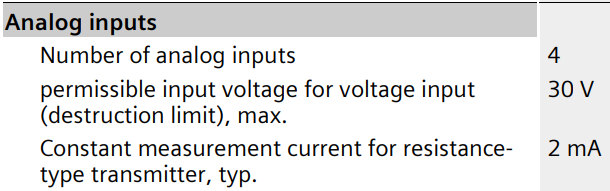
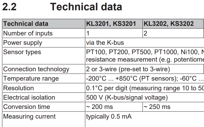
The first thing to check is the datasheet of the device with the resistance measurement input you want to use. Unfortunately, not all manufacturers provide this parameter. Below are examples of controllers with RTD inputs which our customers wanted to use.
The device's datasheet provides the following information. The resistance measurement current is 2mA. The word "constant" may be misleading, as it refers to a constant current value, not its duration. These RTD inputs gives a 2mA measurement current in pulses by switching it between other inputs – this has been verified by one of our customers. For this reason, the SIM-R-MUX type should be used to work with this controller.
The device's datasheet provides the following information. The resistance measurement current is 0.5 mA. There's no information on whether this is a short current pulse of this value. To avoid problems, use the SIM-R-MUX type, just in case.
EDIT: After contacting the manufacturer, we were informed that the measurement current is constantly flowing in the connected sensor circuit. Therefore, Simulator-R can be used.
The device's datasheet doesn't specify the current value for measuring the resistance of the connected Pt100 sensor. One of our customers, wanting to use our resistance simulator, brought the device to us for testing. Measurements showed a constant current source of ~0.17mA at the input. The customer ordered one Simulator-R for testing and then ordered another 16 units.
Typically, the RTD input circuit is a current source (with a constant current value) or a voltage source E with a series resistor Rs (then the current value changes depending on the connected resistance).
If the datasheet does not provide information about the resistance sampling current, you can measure it with a simple multimeter.
If the voltmeter/ammeter readings are close to zero when making the following measurements, it probably means that the RTD input is giving a pulsed measurement current (which the multimeter cannot measure and averages to zero). In this situation, all that remains is to make the following voltage measurements using a probe with an oscilloscope.
The RTD input can be safely shorted with an ammeter. From the input's perspective, this connects a low resistance (fractions of an ohm from the ammeter's shunt), so it will not cause any damage. If you are certain the measurement input is a current source, such a measurement is sufficient, providing the Imax value. If you are not sure, it is a good idea to perform further measurements.
Disconnect the wires from the RTD input and measure the voltage at the terminals with a voltmeter. This will give us the E value, which will allow us to secure the simulator's output to the appropriate value.
Connect a resistance of known value Rx (or, for example, a Pt100 sensor with a known temperature – the resistance value can then be read from the sensor's characteristics table) to the RTD input and measure the voltage across this resistance with a voltmeter. This measurement will confirm the correctness of the previous measurements. If the measurement input is a current source, the voltmeter will indicate U=Rx⋅Imax. If the circuit is a voltage source E with a series resistor Rs, the equation U=E⋅Rx/(Rx+Rs) will be obtained, which will determine the value of Rs. This will allow us to adapt the Simulator-R to work with a given RTD input and ensure proper operation.
Both the Simulator-R and SIM-R-MUX simulates resistance from the Rmin...Rmax range defined in the order. Each has its own limitations that determine correct operation in a given application.
When ordering both simulators you need to provide the Imax measurement current. However, this value means something different for each type.
The Simulator-R will operate with any current ≤ Imax (of course, during device configuration, Imax is set with a certain margin).
The SIM-R-MUX, on the other hand, will operate correctly with an Imax current of ±30%. This is due to its design for operation with an intermittent measurement current – a 30% current drop relative to the defined Imax value is interpreted as the end of the current pulse, which causes the set resistance value to be latched.
Resistance simulators, as the name suggests, simulate resistance. They linearly convert an input signal (e.g., 4...20mA) to an output signal Rmin...Rmax. However, resistance temperature sensors such as Pt100, Ni100, NTC, PTC, etc., have a nonlinear resistance-temperature characteristic. Therefore, if you want to linearly simulate temperature (rather than resistance) using a 4-20mA signal, you can use a 10-point table, entering the appropriate coefficients to skew the characteristic to match that of, for example, Pt100 or NTC10k.
This table function is available in Simulator-R, but not in SIM-R-MUX (due to the required speed of this simulator when working with pulsed measurement current).
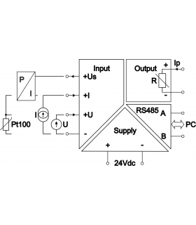
The resistance simulator operates on the principle of Ohm's law - it measures the measuring current Ip, based on the control input signal it knows the Rx value it should simulate, so it sets the voltage Ux=Ip⋅Rx, which is measured by the RTD input of the PLC controller.
The Simulator-R has no Ux voltage limits, while the SIM-R-MUX can only achieve Ux ≤ 2.4V. This is not a problem when simulating a Pt100 sensor, as these sensors are typically measured with a current of ≤ 2mA (so the measuring current is not additionally heating up the sensor) and the maximum sensor resistance is 390.48Ω, which gives a Ux below 1V. However, if you want to simulate higher resistance values, you should verify your input's measuring current and check this voltage condition.
We often receive inquiries about Pt100 sensor duplicators. In such situations, the facility typically has an existing measurement system consisting of a Pt100 sensor measured by a controller. The facility is being modernized, and this temperature information needs to be entered into a second, newly installed controller without significantly interfering with the existing system.
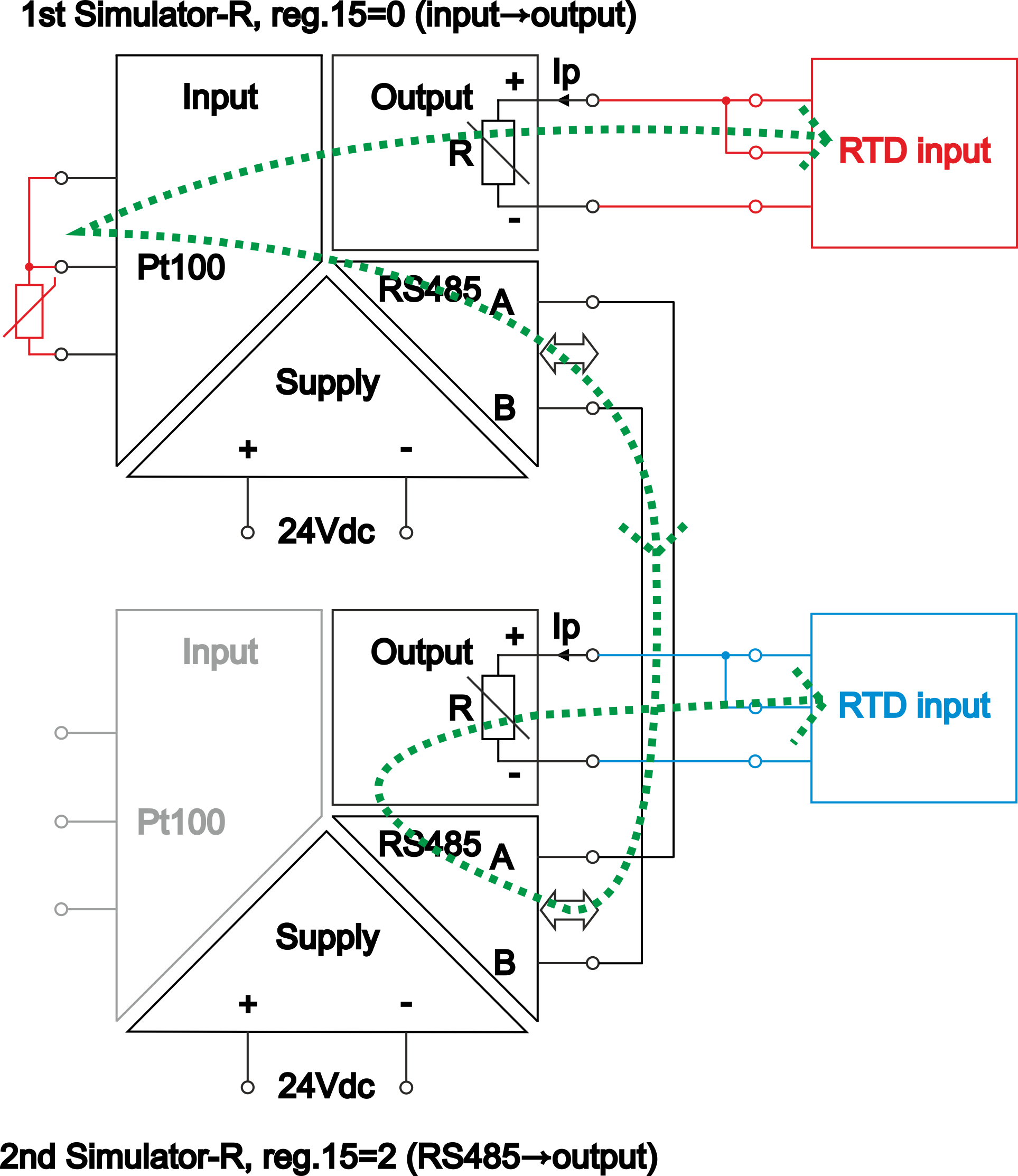
We do not offer a device that would measure an existing sensor and drive two Pt100 outputs to the same value. However, we can offer two simulators (Simulator-R or SIM-R-MUX) that provide this functionality.
You should connect one resistance simulator in series with the old circuit. Connect a Pt100 sensor to its input, and it will achieve the same 1:1 resistance at its output, ensuring proper operation of the old controller. The second simulator should be connected to the first via RS485. In the second simulator, control of the simulated output should be set not based on the input signal, but on values read from the appropriate register of the first simulator via Modbus RTU. This will create a second, separate output simulating the Pt100 in exactly the same way.


Please sign in first.
Sign in