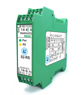
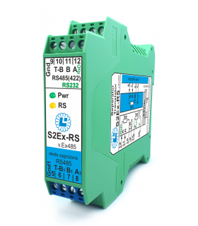

S2Ex-RS v.Ex485
195.00 €
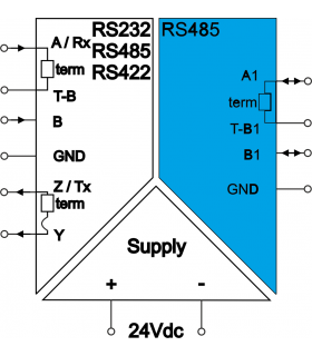
Converter-separator of RS485 transmission on hazardous side to RS232, RS485, RS422, enhanced interference immunity, with intrisically safe barrier Ex atex, with "ia" protection level


The RS485 serial transmission standard is used to transmit data over a twisted pair cable (sometimes with an additional common wire/shield/GND).
Regardless of the letters, the most important thing is the polarity of the lines. Correct RS485 transmission requires that all devices connected to the data bus have the same polarity. In this case, assuming standard line labels, devices should be connected A to A and B to B (all A terminals are connected together, and all B terminals are connected together). However, the standard does not clearly and unambiguously define which line (A or B) should have a positive potential, so manufacturers interpret this differently.
LABOR-ASTER devices equipped with an RS485 transmission connector are marked A-B, where line A has positive polarity in relation to line B. (e.g. S2Ex-RS v.Ex485). This is most often the case in devices available on the market: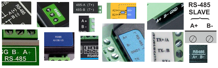
However, there are devices (especially from Western manufacturers) with reverse polarity, where the manufacturer assumed line A as a negative potential with respect to line B:
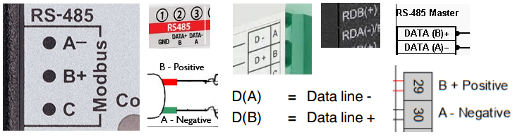
When using devices with RS485 transmission, you should keep this in mind and consciously connect devices to each other, remembering that you should connect + to + and - to -.
We know that we should connect the positive terminal of one device to the positive terminal of the other, and the negative terminals to each other. So, for example, if one device is marked T+,T-, and the other A+,B-, we connect T+ to A+ and T- to B-. If we have two devices marked A, B (without polarity markings), the first step is to connect A to A and B to B.
If, despite the correct baud rates and addresses, you are not receiving RS485 transmission, it is worth trying to swap the wire connections on one device. This will reverse the polarity of the connection on one device, which could be causing the communication failure. Similarly, if you have a working Modbus system and expand it with an additional RS485 device, and communication across the entire system breaks down after connecting it, you've probably connected a device with reversely polarized terminals, causing a conflict on the line.
Because the RS485 standard is based on variable polarity communication, there is no risk of damaging the RS485 circuit by connecting a line with the wrong polarity.
The polarity of the RS485 line can also be checked with a simple voltmeter. Simply turn off the transmission and open the device's A and B terminals. Apply the voltmeter's positive lead to terminal A and the voltmeter's negative lead to terminal B. If the voltmeter reading is positive, it means that terminal A has positive polarity and should be connected to the "+" line of the RS485 bus, and B to the "-" line. If the reading is negative, then B terminal is positive and must be connected to the positive RS485 line.
Please sign in first.
Sign in