


Signal 4...20mA separator - what to pay attention to when choosing?

Analog signal 4...20 mA - what you need to know?
The 4-20 mA analog signal is one of the most commonly used standards in industrial automation. It is a standard way to transmit information about the value measured by sensors and transducers. The signal value is proportional to the measured physical quantity, such as temperature, pressure, or liquid level.
Advantages of the 4...20 mA signal:
- Diagnostics: The minimum signal value is 4 mA, which allows for easy fault detection (a break in the circuit results in a current of 0 mA).
- Ease of integration: It is widely used, which makes it easy to integrate with existing automation systems.
- Reliability: It is immune to electromagnetic interference and other interference, making it extremely reliable in harsh industrial environments.
- Line length: Can be transmitted over long distances without significant loss of quality, which is particularly important in large industrial installations.
Important parameters of the 4...20 mA current loop
There are several parameters to pay attention to when talking about the 4...20 mA signal.
1. Active / passive signal
Whether the 4...20 mA input/output is active or passive tells us where the current loop power comes from.
Active signal 4...20 mA
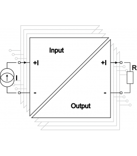
Power from the transmitter: In the case of an active signal, power is supplied by the transmitting device. This means that the transmitter has an internal power source that generates a 4...20 mA signal. A device with an active 4...20 mA output can be symbolically visualized as a current source.
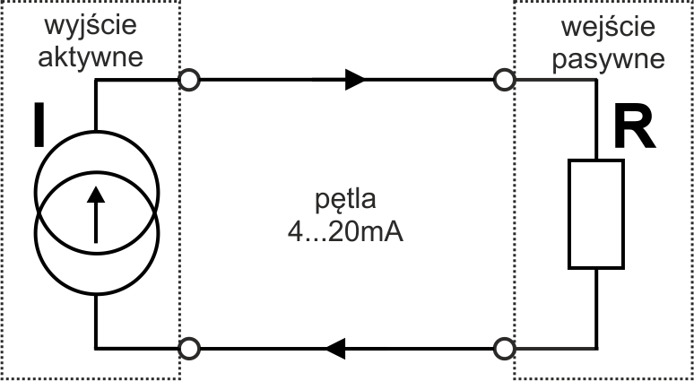
The active output should be connectedto the passive input.
If an active output connects to an active input, there will be a conflict of power sources which will cause the 4...20 mA signal to be incorrect, and the input or output may even be damaged.
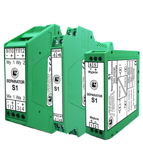
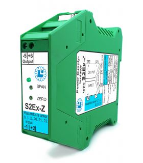
Examples of separators with active output manufactured by LABOR-ASTER:
Passive 4...20 mA signal
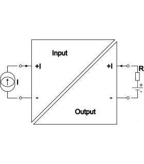
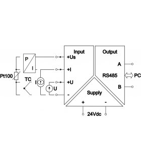
Power from an external source: In the case of a passive signal, power must be supplied by an external source, such as a power supply or an active analog input of a separator or PLC control system. A device with a passive 4...20 mA output is called a two-wire transducer/sensor and can be symbolically visualized as the symbol below.
![]()
The passive output should be connected to the active input.
If the passive output connects to the passive input, the current loop will not have power and the 4...20 mA signal will not flow.
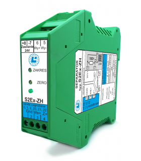
Examples of separators with passive output manufactured by LABOR-ASTER:
2. Current loop supply voltage
Each 4...20 mA current loop must be powered. As mentioned in the previous paragraph, it's important that there's only one power source. Otherwise, a voltage conflict will occur and the 4...20 mA current loop will be disrupted. One of the circuits may even be damaged. It doesn't matter whether the power comes from an active input, an active output, or an external power supply connected in series to the loop.
Voltage balance - minimum supply voltage required for a 4...20 mA loop
When selecting devices in a 4...20mA circuit, it's important to consider the voltage available in the current loop. The principle is simple and follows from Ohm's Law. Multiply the maximum current flowing in the circuit (20mA) by the sum of all resistances in the circuit. Add any other voltage drops in the loop to this result. This sum should be less than the available current loop supply voltage.
Two-wire 4...20 mA sensors and transducers (i.e. those with a passive output and requiring an external current loop power supply) typically have a specified permissible current loop voltage range. The minimum value specifies the voltage required for proper operation at a maximum current of 20 mA. The maximum value specifies the voltage that should not be exceeded to avoid damaging the device.
Example:
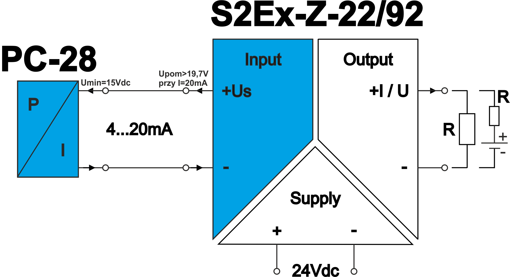
The facility is equipped with an Aplisens PC-28 SAFETY pressure transmitter in Ex version. According to the catalog card, it has a two-wire (i.e. passive) 4...20 mA current output and requires a current loop voltage in the range of 12...28 Vdc. Turning on the display backlight causes an additional voltage drop of 3 V.
This means that a voltage of >15Vdc (12V+3V) is needed for the transducer to operate properly to its full potential. To correctly measure this signal, the separator input should be active (providing current loop power) and providing at least 15Vdc at 20mA (the harshest conditions).
In this case, the separator type S2Ex-Z in the S2Ex-Z-22/92 version should be used (the choice of this version is due to ATEX requirements, which are not discussed in this article). According to the datasheet this design provides a current loop voltage of at least 19.7 Vdc at a current of 20mA, so the required minimum current loop voltage of 4...20 mA is met.
Load capacity - the maximum resistance that the active output 4...20 mA can handle
Active 4...20 mA outputs are the sources of current loop voltage. However, the voltage available to other devices connected in series to the current loop is usually not provided. This information is given as the load capacity expressed in units of max resistance Rload [Ohm]/[Ω]. This can be converted to available voltage by multiplying Rload by Imax = 20mA.
Example:
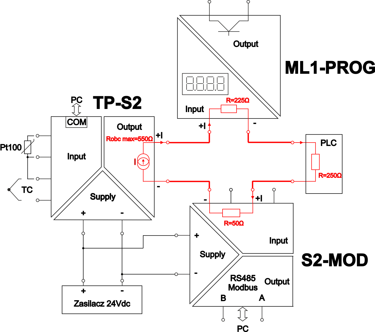
The temperature transducer type TP-S2 in the TP-S2-R version (input e.g. Pt100 temperature sensor; active output 4...20mA) has in the datasheet the output load capacity given as 0...550Ω. This means that a maximum sum of 550Ω loop resistances can be connected to this output (available loop voltage is: 550Ω ⋅ 20mA = 11Vdc). A higher resistance value will result in incorrect operation at the upper current range.
With this information, we need to check the input resistance of the device to which we want to input this active 4...20mA current signal. Typically, the input resistance (e.g., in a PLC controller) does not exceed 250Ω.
Then there is a reserve of 550Ω-250Ω=300Ω, so you can, for example, connect an indicator type ML1-PROG in series, which will present the measured temperature value on its display (the temperature of the Pt100 sensor has been converted into a 4...20mA current flowing through the ML1-PROG input). In its datasheet the specified input voltage drop is 4.5V, which corresponds to a resistance of 4.5V / 20mA = 225Ω, which means the resistance balance is still within the permissible range.
There is a reserve of 550Ω-250Ω-225Ω=75Ω, so you can try to connect the input of the S2-MOD converter in series (because the current input resistance is 50Ω), which will enable reading the measured temperature via RS485 Modbus transmission.
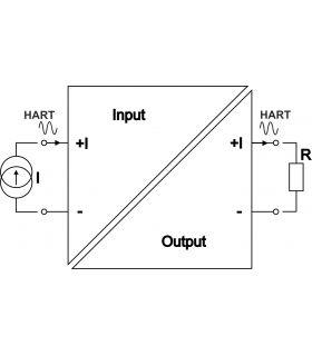
3. Signal 4...20 mA with HART protocol transmission
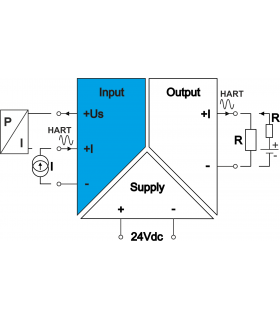
The last thing to consider when selecting a 4...20 mA signal isolator is whether the HART transmission protocol will be used in the current loop.
HART (Highway Addressable Remote Transducer) transmission is a communications protocol used in industrial automation that enables bidirectional communication between measuring devices and control systems. The HART protocol combines both an analog 4...20 mA signal and a digital signal, allowing for the transmission of additional diagnostic and configuration information without interfering with the primary measurement signal.
If so, the separator's description should clearly state that it is transparent to the HART protocol or that it supports a 4...20mA + HART signal.
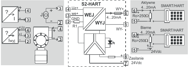
Separators of signals 4...20 mA + HART manufactured by LABOR-ASTER can be seen here:
a) Non-Ex version
Link: Non-Ex analog separators with HART transmission
b) Ex version


Stefan Ziomalski 2025-03-06 Reply
Dzień dobry,<br /> <br /> Dziękuję za ciekawy i merytoryczny artykuł dotyczący separatora sygnału 4-20 mA. Ogólnie rzecz biorąc, tekst prezentuje solidną wiedzę techniczną. Zauważyłem jednak, że niektóre zagadnienia, takie jak szczegółowe parametry izolacji sygnału oraz ich wpływ na kompatybilność z różnymi urządzeniami, mogłyby być omówione nieco bardziej precyzyjnie. Warto byłoby rozwinąć również kwestie praktycznych zastosowań w specyficznych warunkach przemysłowych, co dodatkowo ułatwiłoby zrozumienie tematu osobom mniej obeznanym z tą problematyką.<br /> <br /> Pozdrawiam,<br /> Stefan Ziomalski